Abstract. The
goal of this paper is to show how it is possible to combine the advantages of
the B method in order to design secure[1]
digital circuit that may be easily developed and does not need a design test.
The circuit design may be based on the libraries of well-known circuit design
language like VHDL. Our goal is to make use of B method to produce the
electronic or numeric circuits. At the beginning, the circuit specifications
are written in the abstract machine. The refinement direction is determined by
the basic elements which are used to construct the desired circuit. So the
designer can orient the development to the needed level. This level can be
found as a basic library in B. We demonstrate how VHDL packages can be translated
as B circuit components for giving to the designer a high-level view. Using
this approach, one can develop a circuit of which each part of the specification
has proved to be correct. From the B model it is possible to generate the VHDL
code.
Introduction
The
B method due to J.R Abrial [3] is a formal method for the incremental development
of specifications and their refinements down to an implementation. It is a model
based approach similar to Z [12] and VDM [8]. The software design in B starts
from mathematical specifications. Little by little, through many refinement
steps ([10]), the designer tries to obtain a complete and executable
specification. This process must be monotonic, that is any refinement has to be
proved coherent according to the previous steps of refinement. The abstract machine [2] is the basic element
of a B development. It encapsulates some state data and offers some operations.
The description of an abstract machine is composed of three parts,
·
the declarative part which
describes the states and their properties,
·
the execution part which
introduces operations,
·
and composition clauses.
In
the B development, the proofs accompany the construction of software. Each time
an abstract machine is defined or modified, there are proof obligations related
to its mathematical consistency; if the machine is a refinement or an
implementation, there are also proof obligations of its correctness with
respect to the previous steps of the development chain. The B tool allows us to
generate automatically the proof obligations (noted PO) for each abstract
machine. Generally speaking, the proof obligations will be more and more
complex as concrete details are introduced. Then these proof obligations are
discarded either automatically for the simple ones or in cooperation with the
designer for the complex ones. So, at the last refinement called the
implementation, we obtain secure software which does not need to be tested. At
this low level stage, it may be easily translated to a programming language.
AtelierB or BToolKit are provided with C, C ++ or ADA automatic translators.
But it is possible to extend this code generation to the VHDL language. In this
case, we obtain the possibility of co design between the B method and VHDL.
On
the other hand, VHDL (VHSIC Very High Speed Integrated Circuits Hardware
Description Language) ([1] and [4]) is an IEEE Standard since 1987. It is
"a formal notation intended for use in all phases of the creation of
electronic systems [...] it supports the development, verification, synthesis,
and testing of hardware designs, the communication of hardware design
data…"[2].
VHDL is a programming language used to express the hardware components with a
high level of abstraction. It is a good utility to describe the integrated
circuits, or complete system of hardware and software. Also it can be used to
declare the circuit behaviour.
The
second section of this paper is devoted to showing the cross fertilisation
between the circuit design methodology and the B method concepts. At first, a
simple circuit design, the NOT port, is chosen to show how the B concepts may
be used to produce a simple circuit. Then an example of a multiplexer design is
used to show how a complex circuit may be designed. After that, the methodology
of the circuit design is presented. In the third section, the standard VHDL
package, the STD_LOGIC_1164 is
transposed in the form of a B library[3]
as an example to be used as a set of B elementary components. In the same way,
other VHDL packages can be translated as B circuit components in order to give
to the designer a high-level view. Using this approach, one can develop a
circuit of which each part of the specification is proved to be correct. A B
circuit may be easily improved and it may be integrated with the other elements
in the environment to satisfy safety conditions. The last section of this paper
summarises this work and shows its advantages and disadvantages. This paper
continue the previous work described in [6] and in [5].
Modelling of digital circuits
This
section describes and models some synchronized basic components which will be
then reused. A synchronized circuit is view as a box, within which an (or more)
input line is entering, and out of which an output line (or more) is emerging.
A synchronized circuit is supposed to be synchronized by a clock. Then an
example of more complicated circuit is used to show who man components may be
connected. In both examples the same methodology is used. This methodology is
presented as a table at the end of this section. Using VHDL terminology, a
module is called entity and one entity is coded in one B abstract machine. All
the inputs and outputs are called ports.
Modelling
of a basic logic gate, Not. The Not component
is the simplest logic gate. It has one input and one output. The output is the
negation of the input.


Figure 1. Not gate
The
Not gate is described by a graphical specification (sees the figure 1), but we
can complete these specifications with a boolean expression that described the
behaviour:
(in = 0 Þ
out = 1) Ù
(in = 1 Þ
out = 0)
The
input/output values are boolean. They may have the values TRUE or FALSE. We can
use the last expression to write a B abstract machine. This abstract machine
contains the abstract specifications of the desired circuit (or software):
MACHINE
B_Not_0
DEFINITIONS
Compute_(xx,yy) ==
( ((xx = TRUE) => (yy = FALSE))
& ((xx
= FALSE) => (yy = TRUE)) )
VARIABLES
in, out
INVARIANT
in: BOOL
& out : BOOL & Compute_(in,out)
INITIALISATION
in, out :(
in: BOOL & out: BOOL & Compute_(in,out) )
OPERATIONS
In ( val ) =
PRE
val :
BOOL
THEN
in,out
:( in :
BOOL & in = val & out: BOOL
&
Compute_(in,out) )
END;
val ßOut
= val := out
END
In
this abstract machine the input and the output are represented by the global
variables in and out. These variables can be assigned by all of the defined
operations. Each output is attached to a read operation and each input is
attached to a store one. The environment of the circuit will use these
operations to know the circuit output or to change the input. So we choose In
and Out as names to these operations. The behaviour of the port is
described using the Compute_ definition[4],
which gives us the possibility to express systematically the definition of the
function. In the declarative part, the state is described with the set
theoretic model and the first order logic. The INVARIANT clause states the
static laws, in our case the properties, that the data must obey whatever the
operation that is applied to it. This abstract machine is automatically proved
by the B tool; two proof obligations are generated for the INITIALISATION
clause and two others for the In
operation. This abstract machine is not deterministic since we use the operator
list_var : ( predicate ) in the INITIALISATION and OPERATION clauses.
This operator indicates that the list of variable become such that the
predicate is true. We can generalize this method for any combinatory logical
circuit, for the complex ones as well as for the simple ones. We build a
library that contains the standard ports, structure which is
based on the last machine form.
Given
a circuit (and its abstract and logical specification), we used the following
modifications:
·
The additions of the
operations associated to the supplementary ports; the circuits have more than
one port in general, so we use in_1; ..; in_n to mention the n in
ports of the circuit and out_1;..;out_m to mention the m out
ports.
·
The modification of the Compute_
definition corresponding to the logical specification.
The
following table lists the definitions used in the B components that we defined
before. The calculations are just boolean evaluations of predicates. During the
use of these definitions, the formal parameters xx, yy, …, zz
are instantiated by the names of global variables being associated with the
ports of the circuit.
|
Name |
Port |
Compute_ |
|
AND |
2 in |
bool ( ( xx = TRUE )
& (yy = TRUE)) |
|
AND |
3 in |
bool ( ( xx = TRUE )
& (yy = TRUE) & (zz
= TRUE)) |
|
NAND |
2 in |
bool (not((xx = TRUE ) & (yy = TRUE))) |
|
NOR |
2 in |
bool (not((xx = TRUE ) or (yy = TRUE))) |
|
OR |
2 in |
bool ( (xx = TRUE ) or (yy = TRUE)) |
|
OR |
3 in |
bool ( (xx = TRUE ) or (yy = TRUE) or (zz = TRUE)) |
Table 1: Some basics circuits defined by a boolean equation.
This
method may be used for any logical circuit, for the complex ones as well as for
the simple ones. We build a library that contains all standard gates, structure
which is based on the method described below. Using the Btool the coherence of
theses B abstract machines is proved.
Figure 2. Graphical Symbol of two inputs multiplexer
Modelling
of complex circuit: a multiplexer. A multiplexer
circuit is used in this section as an example to show how to reuse components
previously modelled in order to obtain complex integrated circuits. Basing
ourselves on the logical specification of a component, we can supply an
assembly of many simple components to achieve the desired function. This is
called the synthesis of a numeric circuit. The multiplexer with
n inputs is a circuit with n principal inputs and one output. The output value
is equal to the value of the input of the number i; i is
determined by other inputs. In our example (n = 2), the input named
Select gives the possibility to choose one of the two inputs a and b.
The
output out equals in_1 if the
selector Select is FALSE and in_2 if it has the value TRUE. We write this:
((Select =
FALSE) => (out = in_1)) Ù ((Select = TRUE) => (out = in_2))
To
describe the abstract machine for the multiplexer we can use one that is
similar to the Not gate which is presented above. Four local variables
may be used to represent the inputs/output: Select, in_1, in_2
and out. So we have three input operations and one output one. The
principal difference between the two machines is the definition of the compute_
function:
MACHINE
B_Mux_0
DEFINITIONS
Compute_(xx,yy,zz,res) ==
bool(
((xx=FALSE)=>(res=yy))
&((xx=TRUE)=>(res=zz)))
VARIABLES
Select , in_1 , in_2 , out
INVARIANT
Select : BOOL &
in_1 : BOOL & in_2 :BOOL & out : BOOL &
Compute_(Select,in_1,in_2,out)
INITIALISATION
Select , in_1 , in_2 , out
:(
Select : BOOL &
in_1 : BOOL & in_2 :BOOL &
out : BOOL &
Compute_(Select,in_1,in_2,out)
)
OPERATIONS
In_1 (val)
=
in_1 , out :(
in_1 :
BOOL & in_1 = val &
out: BOOL &
Compute_(Select,in_1,in_2,out))
In_2 (val)
=
in_2 , out :(
in_2 :
BOOL & in_2 = val
&
out : BOOL &
Compute_(Select,in_1,in_2,out)
)
Gate (val)
=
Select , out :(
Select
: BOOL & Select = val &
out : BOOL &
Compute_(Select,in_1,in_2,out) )
val <-- Out = val := out
END
As
in the B_Not_0 abstract machine the boolean
expression under INITIALISATION clause and INVARIANT clause is the same. We have
four operations. This abstract machine is fully proved by the B tool. The
previous B specification can be refined by just modifying the previous boolean
expression defined in the definition Compute_. We rewrite the previous
boolean expression that describes the 2multiplexor:
out = (in_1 ÙØ(Select))
Ú
(in_2 Ù
Select)
REFINEMENT
B_Mux_1
REFINES
B_Mux_0
DEFINITIONS
Compute_(xx,yy,zz,res) ==
bool((not(xx=TRUE) &
(yy=TRUE)) or ( (xx=TRUE) & (zz=TRUE))
)
VARIABLES
select, in_1 ,in_2, out
INVARIANT
Select : BOOL & in_1 : BOOL & in_2 :BOOL & out : BOOL & Compute_(Select,in_1,in_2,out)
INITIALISATION
. . .
OPERATIONS
In_1 (val) = . . .
In_2 (val) = . . .
Gate (val) = . . .
val <-- Out =. . .
END
The
figure 3 introduces a synthesis for the previous two inputs multiplexer. The simple
circuit machines are used to refine the complex ones. In this example, four
machines are used in the refinement of the multiplexer. The relations between
the components are described under the INVARIANT clause[5].
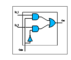
Figure 3. Implementation of two inputs multiplexer
The
next abstract machine is an implementation of the synthesis defines in figure
3. This abstract machine is just a systematic translation which may be done
automatically.
IMPLEMENTATION
B_Mux_n
REFINES
B_Mux_1
IMPORTS
A1.B_And_0,
A2.B_And_0,
O3.B_Or_0 ,
NN.B_Not_0
INVARIANT
select = A2.in2 & select = NN.in &
NN.out= A1.in2 & in_1
= A1.in1 &
in_2 = A2.in1 & A1.out =
O3.in1 & A2.out= O3.in2 & out = O3.out
INITIALISATION
VAR xx, yy, zz IN
NN.In(FALSE)
; xx <-- NN.Out
; A1.In_1(TRUE)
; A1.In_2(xx)
; yy
<-- A1.Out
; A2.In_1(TRUE)
; A2.In_2(FALSE)
; zz
<-- A2.Out
; O3.In_1(yy)
; O3.In_2(zz)
; out <-- O3.Out
END
OPERATIONS
In_1 (val)
= . . .
In_2 (val)
= . . .
Gate (val)
= . . .
val <-- Out =
val := out
END
The
implementation of the multiplexer is made of two And gates called A1 and A2, one OR gate called O3 and one
Not gate called NN which are instantiate in IMPORTS clause. The link between all
ports (multiplexer ports, AND ports ...) is done in the INVARIANT clause. All
operations introduce the multiplexer behaviour, in fact (see after) for each operation;
we define the data propagation between ports.
Gate (val) =
VAR xx, yy, zz IN
NN.In(val)
;
xx <-- NN.Out
; A1.In_2(xx)
; yy
<-- A1.Out
; A2.In_2(val)
; zz
<-- A2.Out
; O3.In_1(yy)
; O3.In_2(zz)
; out <-- O3.Out
END
The
proof obligation generated by the B tool are fully proved and guarantee that
this implementation verify the logic property. We have defined a complete
library for the simple logic elements which may be used for more complex ones[6].
Other's complex examples, such a 4bits ADD, are describes with B method in the
same view, all examples are fully proved.
Modelling
methodology. In this section, our aim is to give a general
method to model a circuit without knowing the details of the desired circuit.
At first the analogy of development between the B method and the numeric
circuits design is presented.
|
Circuits synthesis |
B Method |
|
Functional
Specifications |
Abstract
machine |
|
Architecture
Specification and Behaviour Details |
Refinements |
|
Validation
``functional to material'' |
Proof |
|
Physical Description |
Implementation Machine |
|
Port |
Global Variable |
|
Connection |
Invariant
of relation between variables |
|
Signal Propagation |
Operation
call (transmission of values) |
|
Reusing |
Importation
+ Renaming |
Table 2: Analogy between VHDL and the B method.
In B the initial
specifications of the desired circuit are written in the Abstract Machine using
mathematical expressions. The abstract machine is refined to obtain the first
refinement machine. An abstract machine refinement is performing by determining
the data types or by adding algorithms that satisfies a part of the specifications.
The B tools generate the necessary proofs to demonstrate that the refinement is
correct. Many of these proofs are automatically proved. The others may be
proved in cooperation with the designer. The refinement step may be repeated
many times. More and more the components of the circuit become precise as well
as its behaviour. The result of the last step of the refinement is called the
implementation machine, in which the behaviour of the circuit is deterministic.
The implementation may be TRUTH TABLES; these tables are concise but are not
suitable to describe the large scale circuits; at the same time they need a lot
of proofs. In our methodology we represented each port of the circuit by a
local variable. So that the connection between the ports is represented as a
fixed relation between the global variables. These relations are represented in
the INVARIANT clause which contains all the relations that must be satisfied in
a machine and in its refinements. In the B method the OPERATIONS clause
represents the dynamic part of a machine in which the values of the global
variables may be changed. So signal propagation is done by an operation call.
The B method gives us the possibility to reuse other machines. So many already
defined machines may be reused as components of more complex ones (IMPORTS
clause). An already defined machine may also be renamed and reused by adding
other operations to produce a more developed circuit. Using this method, 80% of
the needed proofs are proved automatically, and the others need cooperation
with the designer. Sometimes little changes of the source machines are
necessary to create the desired proofs. This enables the designer to correct
the possible errors of his design. The general method described in this section
provides the capabilities to define some B abstract machines that modelling the
behaviour of some circuit. But we want modelling some realistic VHDL component
and we need some B abstract machines that correspond to VHDL standard library
such STD_LOGIC_1164.
VHDL libraries
VHDL is one of the most
important tools to describe the electronic circuits. It depends on the
conception of modules. The hierarchy enables the programmer to write the
program as units. Some of these units are elementary expressions which can be
directly compiled. The others may be decomposed into many units. This mechanism
makes the work of team easier, especially when the complexity of the module increases.
A special library is built for each programmer using his correct units which
have been compiled. The programmer may use his libraries and the libraries of
his colleagues and the general libraries. A part of our project is to find
correspondence of VHDL general libraries in B. The following section introduces
one of the most used VHDL libraries, the STD_LOGIC_1164 library and its
equivalent in B.
The STD_LOGIC_1164 Library. The STD_LOGIC_1164 is
standardised by the IEEE. This package defines a standard for designers to
describe the interconnection data types used in VHDL modelling. It was created
to facilitate the portability of VHDL code synthesis. There are nine values in
this logic; each of these values may be assigned to a variable or to a signal.
These values form the extended bit type[7].
|
U |
Uninitialised |
|
X |
Forcing Unknown |
|
0 |
Forcing 0 |
|
1 |
Forcing 1 |
|
Z |
High Impedance |
|
W |
Weak Unknown |
|
L |
Weak 0 |
|
H |
Weak 1 |
|
- |
Don't care Port |
Table 3: values of extended bit type.
An extension of the classic
logic is built to treat these nine values in the VHDL package called STD_LOGIC_1164
instead of two values in the classic one. So the elements of STD_LOGIC_1164
package are:
·
a principal type that contains nine values, many
subtypes which contain some of these values. And complex types which contain
vectors of these types,
·
the basic logic operations over the previous types,
·
and many functions to cast[8]
a type to another,
·
many other functions to solve the problem of the
signals which have many different resources,
·
two functions to determine the direction of the change
of a signal if it is with rising_edge or falling_edge,
·
three functions to decide if a signal is not
determined (if its value is U, X, Z, W or _),
·
the STD_LOGIC_1164 package contains also many
attributes, which are adjectives that may given the language components.
The B components for
STD_LOGIC_1164. The B counterpart of the VHDL STD_LOGIC_1164
library mostly consists in two machines. The first machine, named B_STD_LOGIC_1164_0[9],
contains all the definitions of types and the operations which concern the
extended bit. The second machine, B_STD_LOGIC_1164_VECTOR_0, depends on
the first to define the vectors and the corresponding operations. We also
created a machine, B_Signal_0, to process the signals.
·
B_STD_LOGIC_1164_0 In this machine we define
the principal type STD_ULOGIC as a set of values, and its subtypes as
subsets of this set. We define the subset as CONSTANTS[10].
Under the clause PROPERTIES[11]
we declare the elements of these types. This method of declaration decreases
the number of the necessary proofs which are needed to verify the consistency
of the machine because the expressions under PROPERTIES clause are added as
axioms. The VHDL functions are represented under the OPERATIONS[12]
clause in B. Each operation is a call of a mathematic function. For each
element of the domains we define the correspondent element in the co domain
using tables. We define these tables as constants which have their values under
the PROPERTIES clause. In order to be close to the definitions of VHDL, we
define some functions as compositions of other functions (NAND using NOT, AND).
In order to determine the type of the parameters we use the substitution PRE
pred THEN body END; which enables to verify the type of the input variables. The type of
the output is decided indirectly in the operation in the first affectation
(:=). Each operation consists of a mathematic function call, so the result is
included in the co domain of that function. As opposed to VHDL, the B method
does not accept overloading: VHDL accepts several functions with the same name
but with different signatures, and the wished function is decided only during
the execution depending on the number and the type of its parameters. So in the
B machines of the STD_LOGIC_1164 we have chosen many B operations with
different names, we introduced the type of parameters in these operations as a
part of their names. For example, six functions in VHDL have the name TO_X01. One has an Input variable of
type BIT, another has an extended bit
variable as input and the others have extended bit vector variables as Input.
So we have in these machine two operations: From_std_ulogic_to_X01 and From_BIT_to_X01.
The print operation was inserted to test the value of a variable of std_ulogic
type. The implementation of this operation depends on the designers needs so we
used the substitution skip[13].
in VHDL
Type std_ulogic
IS ('U','X','0','1','Z','W','L','H',' ')
in B
SETS
STD_ULOGIC={ UU,XX,OO,II,ZZ,WW,LL,HH,DD}
in VHDL
SUBTYPE std_logic
IS resolved std_ulogic
in B
CONSTANTS STD_LOGIC
PROPERTIES
STD_LOGIC
<: STD_ULOGIC
& STD_LOGIC=STD_ULOGIC {DD}
in VHDL
SUBTYPE X01 is resolved std_ulogic RANGE 'X' TO '1'
in B
CONSTANTS
XOI
PROPERTIES
XOI <: STD_ULOGIC & XOI =
{XX,OO,II}
in VHDL
SUBTYPE UX01 is resolved std_ulogic RANGE 'U' TO '1'
in B
CONSTANTS
UXOI
PROPERTIES
UXOI <: STD_ULOGIC & UXOI =
{UU,XX,OO,II}
in VHDL
CONSTANT
not_table:std_table:stdlogic_1d:=
('U','X','1','0','X','X','1','0','X')
FUNCTION ``NOT'' (l:std_ulogic)
RETURN UX01 IS
BEGIN
RETURN (not_table(l))
END ``NOT'';
in B
CONSTANTS NOT_STD
PROPERTIES
NOT_STD :STD_ULOGIC > UXOI
&NOT_STD
= { UU |> UU, XX |> XX, OO|>II , II|>OO, ZZ|>XX,
WW|>XX, LL|>II, HH|>OO, DD|> XX }
OPERATION
out ß Not(in)
PRE
in :STD_ULOGIC
THEN
out := NOT_STD(in)
END
·
B_STD_LOGIC_1164_VECTOR_0: In order to deal with the
vectors, we wrote a machine which can use the previous one. Using the SEES
clause, this machine can read all the constants of the seen machine B_STD_LOGIC_1164_0
(i.e.: the tables of the functions). It contains a general function named Apply
which takes four parameters op, in1, in2, out. It applies the operation op,
which is a table function in the previous machine, over all the elements of the
input vectors in1, in2 and gives as output the vector out. We define the vector
as a structure of two elements, the first being a function. Its domain is the
maximum size of the vector and its co domain is the value of the vector
(elements from STD_LOGIC or STD_ULOGIC). The second element is
the size of the vector. We collect all the vectors used in a set with a maximum
size (MAX_VECTOR). Under the OPERATIONS clause we find the correspondent
operations of vector functions in the STD_LOGIC_1164 package. As in the
last machine we can find here a print operation to lay out the desired vector.
in
VHDL
TYPE std_ulogic_vector
IS ARRAY ( NATURAL RANGE <> ) OF std_ulogic;
in
B
CONSTANTS
STD_LOGIC_VECTOR,
STD_ULOGIC_VECTOR ,Max_Element
PROPERTIES
Max_Element:NAT1
&
STD_LOGIC_VECTOR
=
struct (
vector:
1..Max_Element >STD_LOGIC,
vector_size:NAT1
)
& card(STD_LOGIC_VECTOR)<MAX_VECTOR
& !xx.((xx:STD_LOGIC_VECTOR) =>
xx'vector_size<Max_Element)
. . .
in
VHDL
FUNCTION "and" ( l,r : std_logic_vector ) RETURN s td_logic_vector
IS
ALIAS lv : std_logic_vector ( 1 TO l'LENGTH
) IS l;
ALIAS rv : std_logic_vector ( 1 TO r'LENGTH
) IS r;
VARIABLE result : std_logic_vector
( 1 TO l'LENGTH );
BEGIN
IF ( l'LENGTH /=
r'LENGTH ) THEN
ASSERT FALSE
REPORT "arguments of overloaded 'and' operator are not of the same
length"
SEVERITY FAILURE;
ELSEFOR i IN result'RANGE LOOP
result(i) := and_table (lv(i),
rv(i));
END LOOP;
END IF;
RETURN result;
END "and";
in
B
DEFINITIONS
APPLY(op,in1,in2,out) ==
ANY vv
WHERE
vv : STD_LOGIC_VECTOR &
!xx.((xx:1 ..
max(in1'vector_size,in2'vector_size))
=>((vv'vector)(xx)=
op((in1'vector)(xx),(in2'vector)(xx))))
THEN out := vv
END
OPERATIONS
out < And(in1,in2)=
PRE
in1 : STD_LOGIC_VECTOR & in2 : STD_LOGIC_VECTOR &
in1'vector_size =in2'vector_size
THEN
APPLY(AND_STD,in1,in2,out)
END;
·
B_Signal_0: Most of the operations
in the previous two abstracts machines are included in order to find
correspondents to the logic function or to the type converting functions. But
there are other functions in the STD_LOGIC_1164 package which are
related with the electrical signals. So we need to simulate a signal in order
to give a concrete implementation to these functions. The B_Signal_0
abstract machine may be used to solve this problem and could be used as a base
to translate other VHDL packages. Here the signal is expressed in this machine
as a structure of two elements, the first is a value of std_logic type
(or std_ulogic) and the second is a pointer to another structure of the
same type. In order to determine the beginning of the list we define the null
list called nil.
ABSTRACT_CONSTANTS
SIGNAL_ULOGIC , SIGNAL_nil
, F_SIGNAL
PROPERTIES
SIGNAL_ULOGIC = struct
( value : STD_ULOGIC,
next
: SIGNAL_ULOGIC)
& card(SIGNAL) < MAX_SIGNAL
& SIGNAL_nil :
SIGNAL_ULOGIC
& F_SIGNAL : SIGNAL_ULOGIC -->
SIGNAL_ULOGIC
& F_SIGNAL(SIGNAL_nil)= rec(value :DD,
next:SIGNAL_nil)
With these definitions, it is
easy to define an operation which corresponds to the RISING_EDGE
functions which return a TRUE value if the signal value changes from a low
level to a high one. Using the same conceptions the FALLING_EDGE
function is defined to treat the signal in the other direction. As in the other
abstracts machines we defined here the print operation to lay out the value of
the signal in a precise time.
in VHDL
FUNCTION
rising_edge (SIGNAL s : std_ulogic)
RETURN BOOLEAN IS
BEGIN
RETURN (s'EVENT
AND (To_X01(s) = '1')
AND (To_X01(s'LAST_VALUE)
= '0'));
END;
in B
out <-- rising_edge
(in) =
PRE
in
: SIGNAL_ULOGIC
THEN
out
:( out : BOOL & out = bool((in'value
= II)
& ( (F_SIGNAL(in'next))'value = OO)))
END;
The last three B abstracts
machines give the principal characteristics of the VHDL STD_LOGIC_1164 package.
These abstracts machines are fully proved. To be closed to the standard package
we tried to write the B correspondents with the same elements names and definitions.
But because of the differences between the two languages, many points must be
taken of care
1.
The correspondence between the STD_LOGIC_1164 package parts and the B machines parts is not one to
one so we can not transmit some comments which give some details about the
international pragmas of all parts of the STD_LOGIC_1164
package.
2.
The last versions of the STD_LOGIC_1164 contain many attribute instructions. Each attribute instruction
associates a characteristic with a type or with an object. For example:
attribute REFLEXIVE of resolved :function is TRUE[14].
These attributes may be used in the package or in the libraries that depend on
this package. In our machines each time we need these attributes; we use
expressions that gives the necessary characteristics. For the future work when
we will translate the machines that depend on the STD_LOGIC_1164 package we ought to find the necessary expressions
each time we use these attributes.
3.
In VHDL we can use general expressions as: TYPE
STD_LOGIC_VECTOR is ARRAY ( NATURAL RANGE <> ) of std_ulogic, the B method doesn't
give the same capacity. So, for our example, we ought to determine the limits
of the vector range. We do so in the B_STD_LOGIC_1164_VECTOR_0 machine.
In the To_bit function, which converts a given value from extended bit
type to a normal bit type, we give the value xmap to the undetermined
values (U; Z; W;X; ). In the function To_bit the xmap is
initialised to O. It may be redefined in the future only by changing the
function To_bit. To have the same modification in B, we must change the
PROPERTIES clause which is, in the B_std_logic_1164_0.mch, independent
of the To_bit functions.
4.
In many functions in STD_LOGIC_1164 we find the
instruction: ALIAS lv : std_logic_vector ( 1 TO l 0 LENGTH ) IS l we use this
instruction to arrange its input vector so that their elements occupy the first
positions in the local function array. This arrangement facilitates vector
treatments in the function. In B components presented above, we proposed that
the vectors are normally[15]
represented.
5.
The VHDL language gives the programmer the possibility
to prepare an error messages that may be displayed if there is an error during
the execution. In STD_LOGIC_1164, we
have many of these messages. For example : IF ( l'LENGTH
/= r'LENGTH ) THEN ASSERT FALSE REPORT "arguments of overloaded 'nand'
operator are not of the same length" SEVERITY FAILURE;
Example. We present in this
section, how the designer may use the methodology proposed in the previous section
to design a circuit based on the VHDL library. This example is an extension of
an example of the multiplexer proposed before in the first section. Instead of
two boolean values in the first example, TRUE and FALSE, we use an extended bit
with the nine values. In the new proposed example, we describe a multiplexer
with three inputs. The output depends on the value of the input Select_a; it takes the value of In_a
if Select_a equals OO or LL (the low level), it takes the value
of In_b is Select_a equals II
or HH (the high level); otherwise it
takes the value XX (undetermined).
The following mathematic
expression may be summarizing by the definition:
((Select_a = OO Ú Select_a = LL) => (out = in_a))^
((Select_a = II Ú Select_a = HH) => (out = in_b))^
((Select_a = UU Ú Select_a = XX Ú Select_a = ZZÚ
Select_a = WW Ú Select_a = DD) => (out = XX))
MACHINE
B_Mux_STD_0
SEES
B_STD_LOGIC_1164_0
DEFINITIONS
Compute_(xx,yy,zz,res) ==
( ((xx = UU) => (res = XX))
& ((xx = XX) => (res = XX))
& ((xx = OO) => (res = yy))
& ((xx = II) => (res = zz))
& ((xx = ZZ) => (res = XX))
& ((xx = WW) => (res = XX))
& ((xx = LL) => (res = yy))
& ((xx = HH) => (res = zz))
& ((xx = DD) => (res = XX)) )
. . .
END
Comparing the specifications
of the multiplexer in the two examples, we find the following differences:
1.
In the new machine, the SEES clause is used to enable
us to use the variables of the B_STD_LOGIC_1164_0 machine.
2.
The type of the four local variables is changed from
the boolean type to the STD_ULOGIC type defined in the B_STD_LOGIC_1164_0
abstract machine.
3.
The definition of the function Compute_ is redefines
and extended to cover the nine values of the extended bit. The following B
abstract machine contains the specification of this multiplexer[16].
Conclusions
Some limitations. To develop an electronic
circuit in B requires understanding the refinement calculus, that is, a certain
adaptation time for a circuit designer. Most recent imperative languages like
VHDL include facilities as manipulation of a vector without explicit length or
functions with various signatures. Because the B method does not include such
features, these differences induce difficulties in transforming VHDL to B. One
solution to the problem of vector length is used in the B_STD_LOGIC_1164_VECTOR_0
by passing the length as a parameter and by using the universal quantifier ("). To design circuits, a large quantity of proofs may
be generated and must be proved automatically or in cooperation with the
designer. The size of these proofs depends on the quality of the program, the
capacity of the prover, the designer, and the tool we use. For very large
circuits, the number of the necessary proofs could be extremely large.
When the circuit is designed
in B, we can prove that it satisfies the required specifications but we have
not yet any tools to create the real circuits directly from the B
specification. But with B method it is possible to represent the circuits as
near as it is needed to the physical level. In [6] authors refined the B_NOT_0
abstract machine based themselves on abstracts machines of CMOS transistors. To
simulate a signal propagation, the conception of the time must be represented some
ware. In this report a list of extended bit values is used to represent a
signal. For more complicated cases when it is necessary to treat many signals
in the same time, a list of structure may be used to represent each signal.
Each structure consists of a value and a date. A global clock may be used to
control the harmony between all the signals of the circuit.
Advantages. The most important
characteristic of the B method is that it produces a secure circuit. The
circuit which are obtained in the implementation satisfies 100% the
specifications in the abstract machine. It is possible to add the required safety
conditions under the INVARIANT clause in the abstract machine. So the circuit
design is completely correct. The error may occur only when we describe the
specifications or if the physical circuit does not correspond to the proposed
model. The cost and the time of the test are won. To develop a circuit that was
proved before, it is enough to prove only the new characteristics. It is not
necessary to reprove all the old ones. So the designer may use all the circuits
which are designed before, he can make some changes and then prove a small part
related to the new characteristics. The B tools can automatically decide which
parts of the model are changed or added in order to be reproved. This
characteristic is quite important for the necessary modifications of the
integrated circuits development. The B method is used in many domains. Often
the systems to design are composite, both mechanical and electronic, software
and hardware. For example the design a circuit to control a robot which
satisfies some needs and conditions of mechanic and electronic. This may be
easier to design using the adequate B libraries like which we have specified
for digital circuits in the same time with mechanical libraries.
Future Work We intend to
create a simple and complex example to show the refinement development of a
circuit design from the abstract specification to the physical level. In such
example, we intend to show the refinement by introducing algorithm[17].
Also we intend to create several libraries in B equivalent to the VHDL libraries,
in order to facilitate the circuit design in B. Furthermore this facilitates
the transformation operation from B to VHDL. We try to find a common rule which
may be used to automatism the translation. Also we may solve this problem by
creating a physical library in B that contains the characteristics of the basic
electronic elements or by retranslating the results of a circuit development
from B to VHDL. Semiautomatic translation of similar circuit specification to
B abstract machine is another way of work. In a first step, we define the
properties of the new components. The second step, is graphical, it introduce
the components synthesis by composition of basic components. So, at the last
refinement, the implementation, we obtain a secure software, it may be easily
converted to another programming. We want define a tool hat provide the
possibility of an automatic transformation of the implementation to VHDL
language. In this case, we obtain the possibility of co design between the B
method and VHDL.
Summary In this paper, we presented a
part of our work to create B libraries which correspond to some VHDL packages,
as the STD_LOGIC_1164 package. This project enables us to take advantage of the
power of the B method to develop a secure circuit. We write the specification
of a desired circuit, and then little by little we refine our specifications to
reach to the implementation of this circuit which depends on the desired
libraries. The AtelierB or the Btoolkit enables us to generate the necessary
proofs to verify that each description of our circuit is consistent and each
step of the refinement satisfies the conditions of the previous one. That
implies that it satisfies the specifications in the first description. These
proofs may be generated automatically or in cooperation with the designer. At
the end we obtain a circuit that satisfies our needs. The development from the
abstract specifications to a complete circuit description does not need an
expert in circuits but a B expert. B lacks some programming language
characteristics as the type casting and the generality quality. But on the
other hand, one of the B designing advantages is that a change of an old
circuit needs proofs corresponding only to the new modifications. Also we can
reach the desired specifications using a mix between electric and
electronic libraries.
REFERENCES
[1] Standard VHDL Reference
Manual. IEEE, 1993.
[2] JeanRaymond
Abrial. On constructing large software systems. In
Algorithms, Software, Architecture. Information Processing 92. IFIP 12th World
Computer Congress, volume A12, pages 103--12, 711 Sept. 1992.
[3] JeanRaymond
Abrial. The B Book Assigning Programs to Meanings.
Cambridge University Press, August 1996.
[4] R. Airiau,
J.M. Bergé, V. Olive, and J. Rouillard.
VHDL Langage, modélisation, synthèse.
Collection Technique et scientifique des télécommunications. Presses
Polytechniques et universitaires romandes, 1998.
[5]
JeanLouis BOULANGER, Ammar
Aljer, and Georges MARIANO. Conception sûr de circuit basée sur la notion de
propriété. 14 ème journée internationales Génie
Logiciel & ingénierie de systèmes et leurs applications, du 4 au 6 décembre
2001, ICSSEA 2001, 2001.
[6]
JeanLouis BOULANGER and
Georges MARIANO. Modélisation formelle de circuit
numériques par la méthode b. Technical Report
199925RT, 1999.
[7] M. Ducassé
and L. Rozé. Proof Obligations of the B Formal
Method: Local Proofs Ensure Global Consistency. In Proceedings of the
LOPSTR'99, pages 10--29. SpringerVerlag LNCS,
September 1999.
[8] Cliff B. Jones.
Systematic Software Development Using VDM. PrenticeHall
International, Englewood Cliffs, New Jersey, second edition, 1990. ISBN 0
138807337.
[9] Christoph
Kern and Mark R. Greenstreet. Formal Verification in
Hardware Design. Presses Polytechniques
et Universitaires Romandes, 1998.
[10]
C. Morgan. Deriving programs
from specifications. Prentice Hall International, 1990.
[11]
Félix Nicoli. Vérification formelle de descriptions
VHDL comportamentales. PhD thesis, Provence University, July 1999.
[12] J. M. Spivey. The Z
Notation: A Reference Manual. Prentice Hall International Series in Computer
Science, 2nd edition, 1992.
[13]
STERIA. Manuel de Référence du B. Steria,
September 1998.
BIOGRAPHY
Mr. Boulanger
Jean-Louis is
currently project manager within the framework for the software validation within
the first laboratory accredited by the COFRAC[18]
for carried out six tests within the framework of Program 152. He in particular
took part in the validation of the system METEOR which was brought into service
in October 1998.
Mr.
Mariano George is a researcher in the ESTAS (Evaluation and
Safety of Automated Transport Systems) team to INRETS[19].
He works on specification and validation of critical software.